SUSPENSION
MEASUREMENTS.
By Geoff
Kremer and Kev Rooney
Well! We have gone into detail about suspension geometry; the whyís and a
bit of theory, but what about the howís. We have spoken of camber and caster angles, bump steer etc but not how to really
measure them, so hereís how.
Manufacturers and most major service agents use optical and or laser equipped
measuring instruments, if you can obtain access to such a set up try and get it!
otherwise read on!
First off you donít need much in the way of special tools. A decent steel rule
and a steel tape, a vernier angle gauge and some 1/2" x 1" of
unmarked and dead straight bright steel bars about 24Ē long and a large set
square. Another useful tool is a magnetic angle finder, if you get one meant for
the building industry it wonít cost a fortune
VERY IMPORTANT RULE NUMBER 1
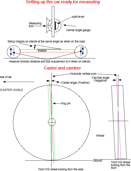
The chassis of the car you are measuring must be
set up accurately. The suspension must be set at the correct deflection for the
car when it is stationary and wet or at kerb weight with preferably the driver
and a front passenger.
TO DO THIS.
A fully road ready car should be parked on level ground with a driver and
passenger sitting in it. Bounce all four corners to settle the suspension,
measure each shock absorber distance from eye to eye and the angle of the
chassis, note it all down. If the chassis surface is a little uneven use one of
the steel bars as a rest.
Please
note!
You must take the chassis angle directly from the chassis, not any part of the
bodywork.
If you have only the rolling chassis then it should be set up with dummy bars in
place of the spring/shocker combination set at the suspension deflection the
finished car will ride at.
NEXT.
The car or chassis must be put onto axle stands.
Set the chassis angle fore to aft to what it should be, putting packing pieces
in to achieve it. Then make sure the other rail is exactly the same so that the
chassis is completely square.
You might be surprised the amount of twist a fully loaded chassis will have if
itís on uneven ground so this is important and hereís why;
All of the suspension geometry is referenced to level ground, not the chassis.
As an example if you need a caster angle of 7 degrees pos and the chassis is
dumped in the weeds at the front only, by 4 degrees, you will end up with total
caster angle of only 3 degrees and possibly a visit to the nearest ditch!
Take all the wheels off and set up each corner of the suspension to what you had
previously noted down.
Theoretically each side should be identical, but if there is a few mmís
difference you should try to even it up. (The best way would be to make up some
dummy bars to take the place of the shockers).
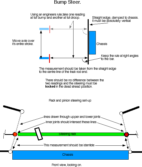
Next, lock the steering rack or box in the exact dead centre of itís travel.
Most racks have a small centring hole that you can put a pin into.
The front wheels should be absolutely parallel and straight, regardless of what
the track rods arms are doing. If they are not then you should adjust the track
rod ends until they are, also each track rod or drag link should be exactly the
same length. This also applies when you finely come to setting up the
ďtoe-inĒ. You should be able to get your local garage to zero the tracking
for you before you put the car on stands.
ADJUSTMENTS.
A lot of American set ups rely on the ability to physically bend bits of the the
suspension to alter individual settings. This makes it almost impossible to
do unless you have the proper hydraulic rams and presses! European cars however, often make use of shims to make things easier. When you
are designing your suspension make sure you can easily alter its parameters,
especially camber and caster!
Perhaps the easiest way is to use shims behind a joint mounting or if you are
going the race route using spherical bearings such as Rose gives you a very
flexible way of tuning suspension, and you must be prepared to maintain them
properly if you want them to last.
A word of warning here. Please don't ever use track rod ends as main load
bearing joints!
Live rear axles also need to be checked especially if the case has been narrowed
or new mounts fitted, this is because when you weld something to a tube such as
an axle case it will distort and bend. One way to overcome this is to lay a bead
or a series of beads of weld opposite where the distortion is until the axle is
pulled in to line. Live axles should not have ANY, caster or camber applied.
When altering the camber and caster, they will often interact so you may have
set the caster up spot on, then adjust the camber only to find the caster has
gone out so you have to keep measuring these two until the readings stabilise.
MEASURING THE SUSPENSION.
Camber
If the top of the wheel leans inwards itís negative camber, if it leans out
itís positive.
For road use the camber setting can be anything between 1 degree positive to1
degree negative depending on the tires you are using.
For most road applications where you are running radial tires, usually about 1/2
to 1 degree negative is ample any more than this and youíll start wearing
tyres out and the suspension starts to get unstable and jittery when cornering.
Beam axles usually run a bit of positive camber, unfortunately there is not a
lot you can do to alter it and if itís miles out you should consider replacing
it.
To measure camber all you do is place your angle finder gauge against the
outside face of the brake disc. The gauge must be kept absolutely vertical. Each
side should be within 15 minutes (1/4 degree) of each other. To ensure an
accurate reading, it would be wise to ďnip-upĒ the wheel bearing nuts to
prevent the end-float from affecting the readings, donít forget to reset the
end float afterwards.
Jaguar rear ends can run up to 1 degree negative and to alter this there are
shims located between the inner UJ flange and the brake disc. There are also
shims behind the bottom arm inner fulcrum mounting boss.
Caster
This is probably the most difficult to get spot on as on 2 of the 3 suspension
systems you have to factor in King Pin inclination (KPI). This is the angle that
the vertical back plate makes relative to the position of the king pin or
macpherson strut. This angle changes as the wheel moves side to side in an
increasing/decreasing figure. This affects the reading you get for caster so
that it must be taken with the wheels in the dead ahead position, many rack and
pinion have a slot into which you insert a pin to hold it dead ahead. This is
only effective if the tracking has been set equally on both wheels rather that
all on one side.
Next we come to the problem of getting a reading on an IFS spindle. Many have a
machined boss for this purpose or alternatively the brake calliper is usually
mounted parallel to the king pin centre line. The easiest, and most effective is
to take car to a tyre shop that has the latest front end laser alignment
equipment and get a read out from them. At least now you know what figures you
have and can then find a suitable point from which they can be obtained.
The Macpherson strut system is the next to check out and the angle gauge can be
placed to the front of the actual strut. This figure is again affected by KPI
but you can at least see from where to take your reading. Depending on how
accurate you gauge is, as you move the steering slightly from the centre you
should get an increase/decrease as the KPI take effect. As both the Mac strut
and IFS set ups allow .5 to 1 degree variation from side to side there is a fair
tolerance. Dial out as much variation as possible, reset to your required
figures and have rechecked.
A beam front end, tube or I beam, is the easiest to measure. As the stub axles
rotate freely of the beam, you can take a reading from the boss that holds the
king pin or across the flat on the top of the king pin.
As a rough guide line you would expect a reading of between .5 to 2.5 on a
Macpherson strut, 3 to 5 degrees on an IFS and 5 to 7 degrees on a beam front.
All of these can be dialed to your personal preference within these parameters.
The more you put in the heavier the steering will be, but also this will give a
greater self-centering effect.


Tech Section
| 
