Combined Stop/Turn Lights
By Geoff Kremer

For those of you want to make your brake lights indicators as well, here is how to do it without it costing a fortune.
First off a little description.
What happens is this:
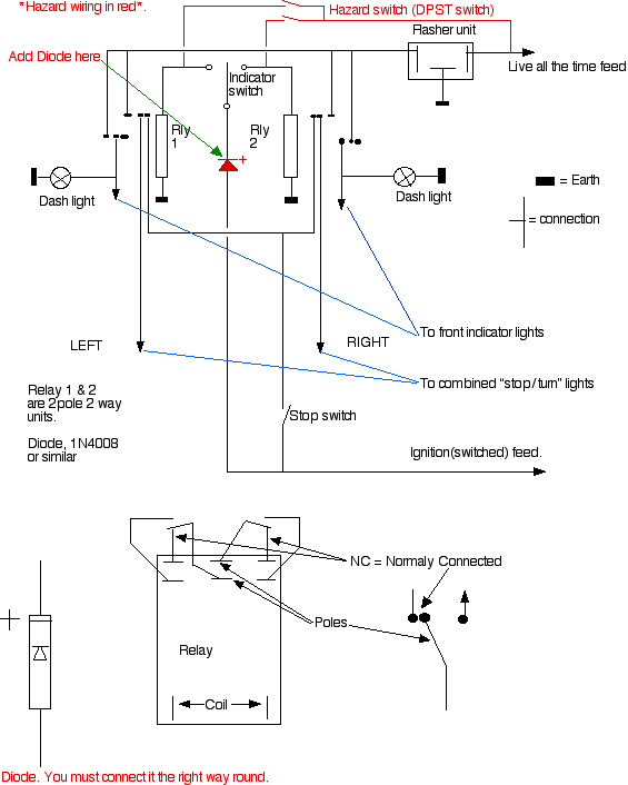
In the non indicating state, both sets of contacts shown closed are connected to both stop lights and the stop switch so when you brake the stop lights behave normally.
When turning, one of the relays is switched over and the stop light to that relay is then connected to the flasher unit. An extra pair of contacts are also closed connecting the front indicators to the flasher unit as well. The other relay, because it’s not activated, allows the other stop light to stay connected to the stop switch and lights up only when you brake.
The extra part in red is for hazard indicators. When in use you will notice that the stop light circuit will be disconnected so no brake lights at all. But then it’s actually illegal to drive with the hazards on anyway.
The relays to use are; 2 pole 2 way 12 Volt continental style items with a contact rating of not less than 3 Amps. You will probably get a 3 pole 2 way unit so just ignore one set of contacts and shouldn't cost more than £2 each. The connections to the various terminals will be marked on the relay and may differ from the diagram.
You will need to solder the connections and all the cable used is 14.030.
The flasher should be a universal electronic item.
The Diode which a one way electronic valve MUST BE CONNECTED THE RIGHT WAY ROUND. Any electronics store will stock them and should cost about 50P. Anything rated at
more than 0.5Amp@500 PIV will do.

Tech Section
| 
