PLANNING
THE WIRING
By Geoff Kremer

Now I’m not going to delve into circuit design because this is a little early in our foray into electric’s but for those of you who know what they are doing this little tip might be of use.
When I plan a new wiring job I get all the relevant facts and needs down on paper so I have a list of all the electrical items on the car. Then I design the basic diagram just to work out the best way of feeding things like fuses and relays
etc.
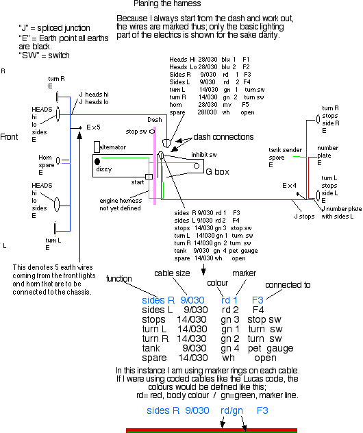
I make a simple drawing of the car with all the electrical items in their respective places. Now this is where you can save yourself a lot of time and grief. Using this drawing I layout the harness runs then I add the wires when and where they appear, what they are connected to and where they come from including wire sizes and colours. This is the main drawing that I work from.
Only later, when everything is up and running do I produce a full circuit diagram for the client.
As you can see from the example, the harness runs are drawn out in the most direct and simple way possible. One end of each run would end at the point where the fuse box and relays hide out, in this instance as with most, it’s the dash. So when you come to run the cables you start at the dash end, in this case, and run the cables, along the way you can see where you have added spliced junctions so you would lay in the wire to be joined. As you see each harness has an additional spare wire marked “open” because it is not connected to anything yet. So at the end of each item say the head lamps you should have 4 wires Hi beam feed, Low beam feed, side lights and an earth at both head lamps. Likewise at the dash end there should be 8 wires. If you break down the harnesses into blocks like this there is less of a risk of leaving a cable out. The colours are abbreviated to red=rd,
white=wh, black=bla ect.

Tech Section
| 
