A SIMPLE HAZARD SYSTEM
By Geoff Kremer

For those of you that would like to fit a hazard warning system to your pride
and joy here is a very simple and effective circuit.
First off a note on the little items that make this so easy; they are called
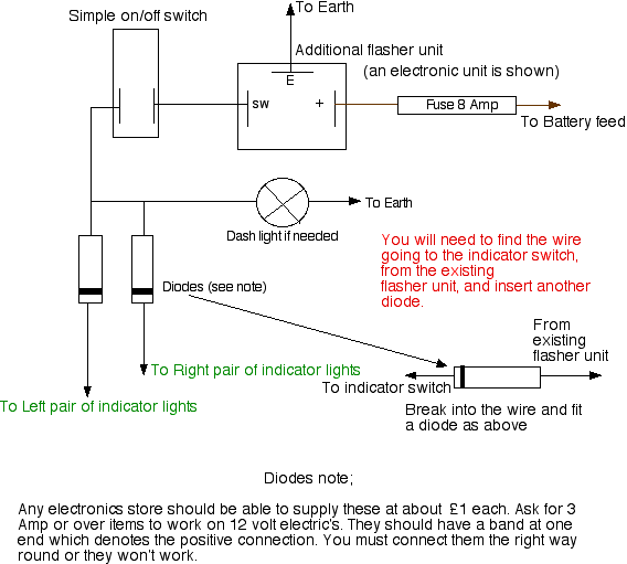
DIODES. These are simply electronic one way valves. Current will only flow
toward the direction marked by the band. They must be wired up the right way
round otherwise the circuit won't work!
You should be able to get them from any electronic parts store such as Maplins
and the ones you need are rated at 4 Amps or more. You may be asked what voltage
you need, called PIV (Peak Inverse Volts), since we are only dealing with 12
volts and most diodes have a PIV of well over 150 volts this should not be
important.
You will need to insert an additional diode in the wire going from your existing
indicator flasher unit to the indicator switch, note the direction of the diode,
this is called a blocking diode and is there to prevent the ignition circuit
being powered up if you have the hazards on and the indicator switch engaged at
the same time.
The diodes will have wire ends to them and these should be soldered directly to
the car's wiring and some sleeving or better still shrink tube slipped over. Do
not crimp terminals to the diodes because the action of the crimp will fracture
the wire ends.
I've shown the circuit using a three terminal electronic flasher unit but the
system will work equally well with the old two terminal ones, make sure you get
one meant for the hazard indicators though.
The switch can be any simple on/off switch capable of passing over 6 Amps at 12
volts DC.

Tech Section
| 
